Accurate data interpretation in Long-Range Ultrasonic Testing (LRUT) relies on distinguishing structural reflections from localized defects. While the technology allows for rapid screening of extensive piping, the presence of features such as welds, supports, drains, and reducers creates a complex signal environment. This application note serves as a diagnostic reference for identifying these common field features based on their A-scan morphology, % CSC (Cross-Sectional Change), and signal symmetry.
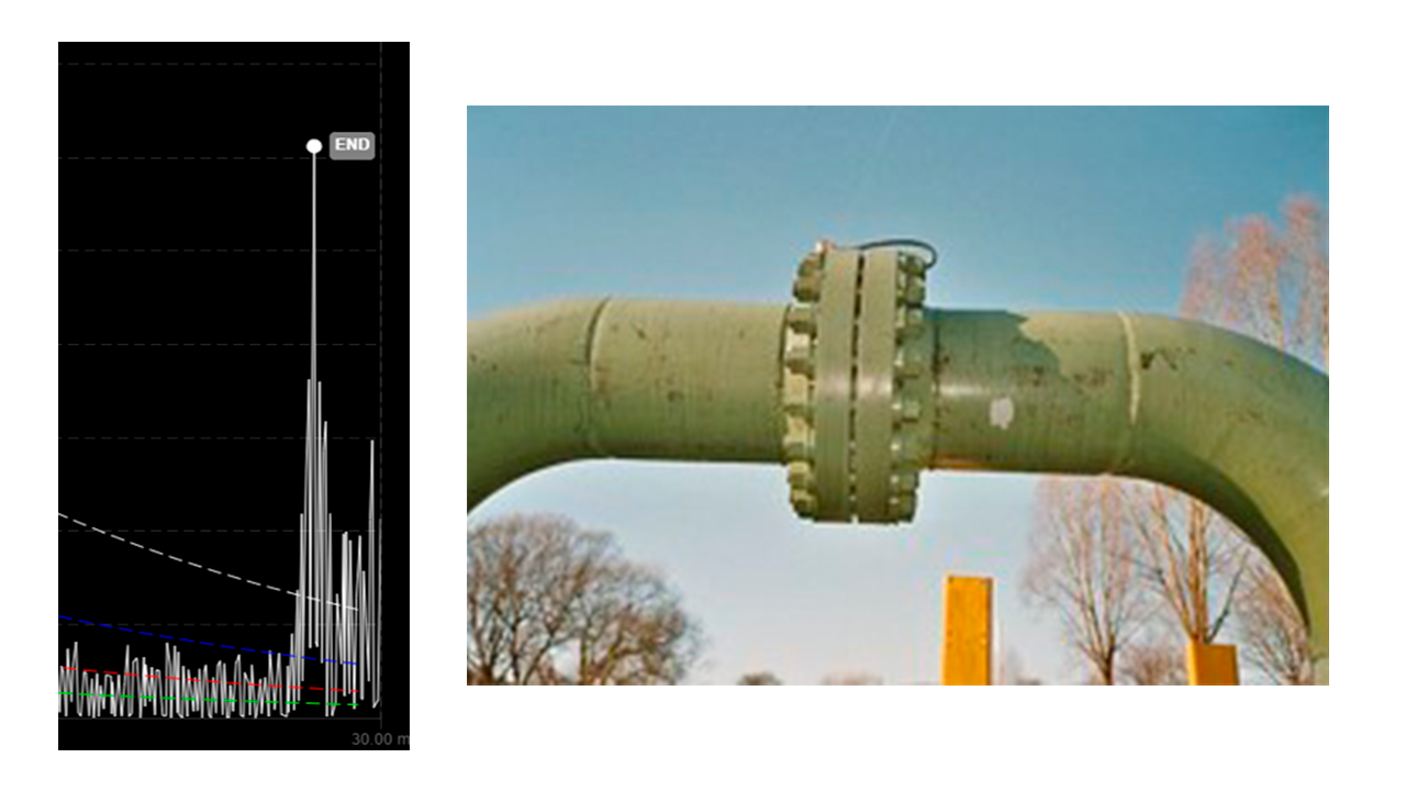
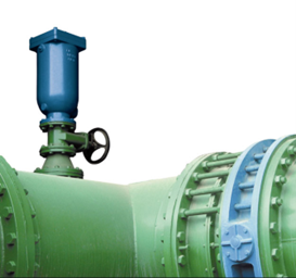
Flanges and final cuts are axisymmetric features that represent the end of the A-scan, as they result in a 100% Cross-Sectional Change (CSC). These features typically produce signals greater than 100% DAC and are characterized by a wide primary echo followed by multiple associated reverberations.
While flanges are not commonly encountered in the field, they are typically found near valve stations or at connections to tanks, spheres, and other pressure vessels.
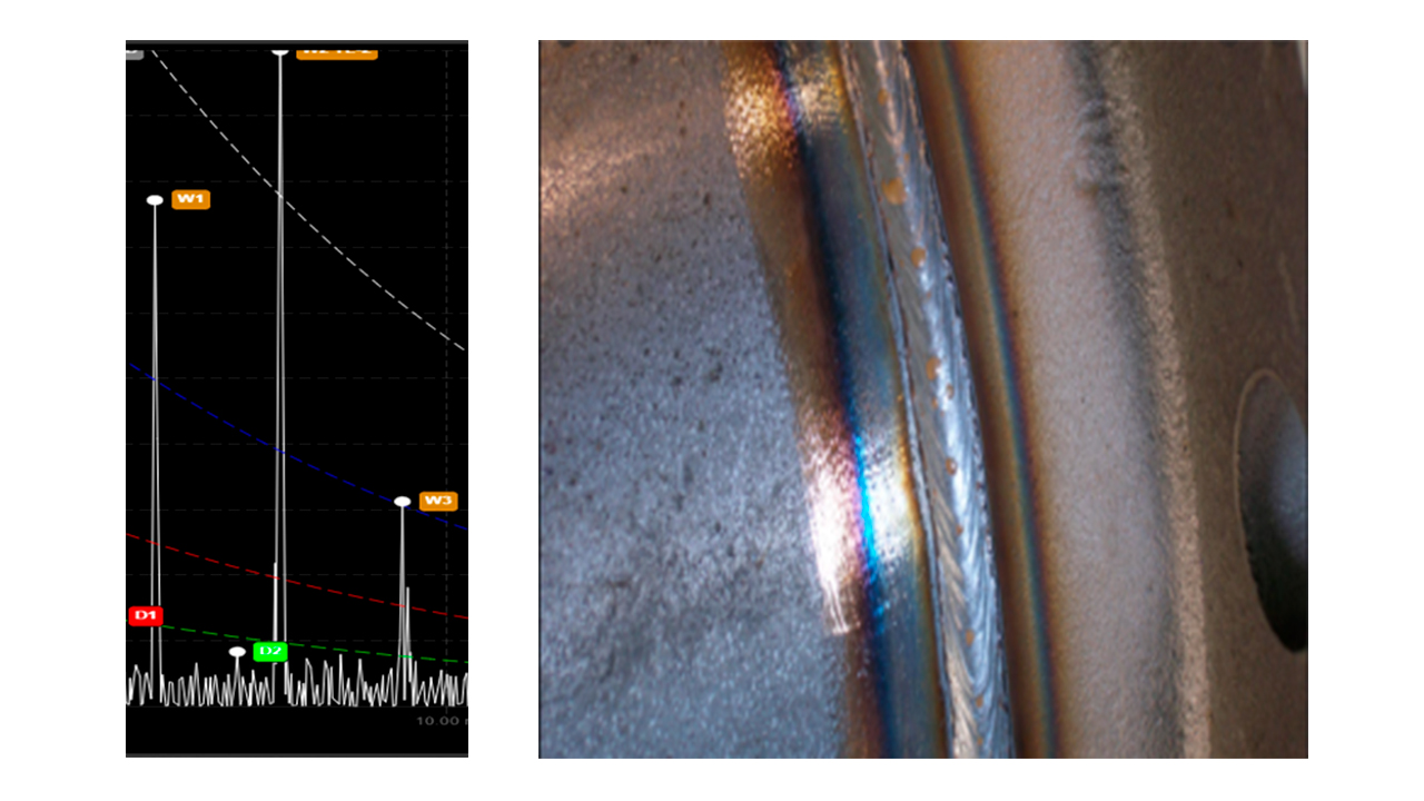
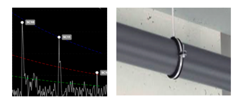
Welds are axisymmetric features that represent a nominal 22% Cross-Sectional Change(CSC). In LRUT, welds are primarily used to fit the DAC curves; a high-quality weld should align closely with the 22% DAC level. On the A-scan, a weld is represented by a medium-amplitude, narrow echo.
As a frequent feature in the field—found at nearly all pipe section connections—welds serve as a critical reference point for estimating defect severity by ensuring the DAC curves are accurately aligned.
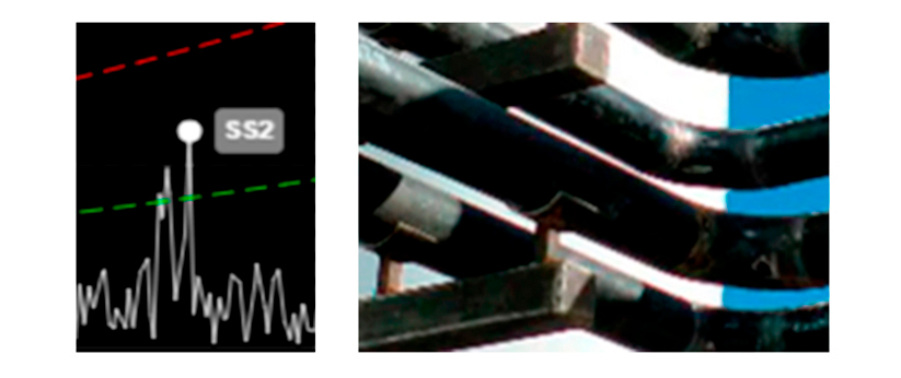
Bends and elbows are commonly encountered in the field at various angles, typically 90° and 45°. While evaluation is sometimes possible after a 90° bend, it is generally not possible after a 45° bend. Therefore, it is standard practice to end the A-scan analysis at the location of a bend.
Bends typically feature two or three welds, depending on the diameter, which generate echoes on the A-Scan. The first echo presents a medium amplitude of 22% CSC, while the second has a low amplitude of under 22% CSC.
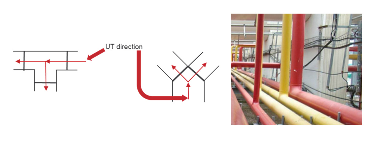
In branches, ultrasonic waves travel in two different directions, and several echoes appear in the A-Scan. These echoes have a medium amplitude—similar to welds—at 25% CSC. The first part is axisymmetric and the second is non-axisymmetric. Features are typically found in deviations of the principal track. This element is typically the end of the A-Scan.
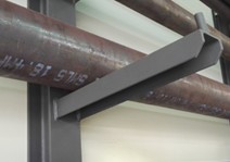
Supports are very common elements encountered in the field and represent critical inspection points, as they are typical areas where corrosion is found and are often inaccessible for direct evaluation using other traditional methods.
For Corrosion Under Pipe Supports (CUPS), the MRUT SH technique—available with the VOLTA 2 inspection platform—is the recommended method. The MRUT SIZING application, also available with VOLTA, is a quantitative method that allows for the estimation of remaining wall thickness.
There are several types of pipe supports. The most common include:
These are typically found at pipe ends or in areas where pressure accumulation is a concern. Drains are installed in piping systems carrying liquids, whereas vents are used for gas-carrying lines. On the A-scan, they appear as narrow echoes with an amplitude up to 15-20%. The % CSC varies depending on the ratio between the nominal pipe size and the diameter of the drain or vent. This non-axisymmetric feature doesn’t affect the length of the A-Scan.
These features are uncommon in the field. They manifest on the A-scan as narrow, medium-amplitude echoes with a typical % CSC of 23%. Signal symmetry is contingent upon the reducer configuration: concentric or eccentric. Concentric reducers behave similarly to welds, whereas eccentric reducers may exhibit characteristics similar to bends. Functionally, reducers are identical to expanders but operate in the opposite flow direction.
Since diameter changes generate significant noise, the signal can usually pass through these features. When these features are present, the A-scan range (length) must be manually defined by the operator.
