Una compañía australiana de GNL tiene muchas tuberías de acometida (riser pipes) en campos de gas situados en ubicaciones remotas. Los risers están envueltos en diversos medios, dependiendo de la tecnología de recubrimiento (wrap) elegida en el momento de su construcción. Actualmente, la política de la compañía de GNL es excavar los risers y retirar el recubrimiento para inspeccionar visualmente las tuberías en busca de corrosión externa.
La corrosión externa ocurre principalmente en la interfaz aire-suelo y en las secciones enterradas donde la humedad y el oxígeno son más prevalentes. La exposición ambiental provoca una oxidación localizada bajo los recubrimientos protectores (wraps) y en áreas enterradas inaccesibles, lo que resulta en un adelgazamiento de la pared que puede derivar en una falla catastrófica. Por consiguiente, se requiere un método de inspección confiable y no invasivo para gestionar estos riesgos.
La excavación de los risers es costosa, consume mucho tiempo y es de alto riesgo, dada la posibilidad de ruptura, liberación de gas a alta presión y explosiones. Por lo tanto, se requería un método de inspección preciso y rentable que no necesitara excavación. La compañía de GNL solicitó una prueba de la tecnología de ondas guiadas de Medio Alcance (MRUT) y/o Largo Alcance (LRUT) para inspeccionar la corrosión en los risers enterrados. El objetivo era sustituir el requisito actual de excavación e inspección visual.
Para esta prueba, se utilizaron tuberías activas que contenían GNL a alta presión. No se proporcionaron criterios de defecto mínimo reportable y no se registraron defectos conocidos en las tuberías de muestra analizadas.
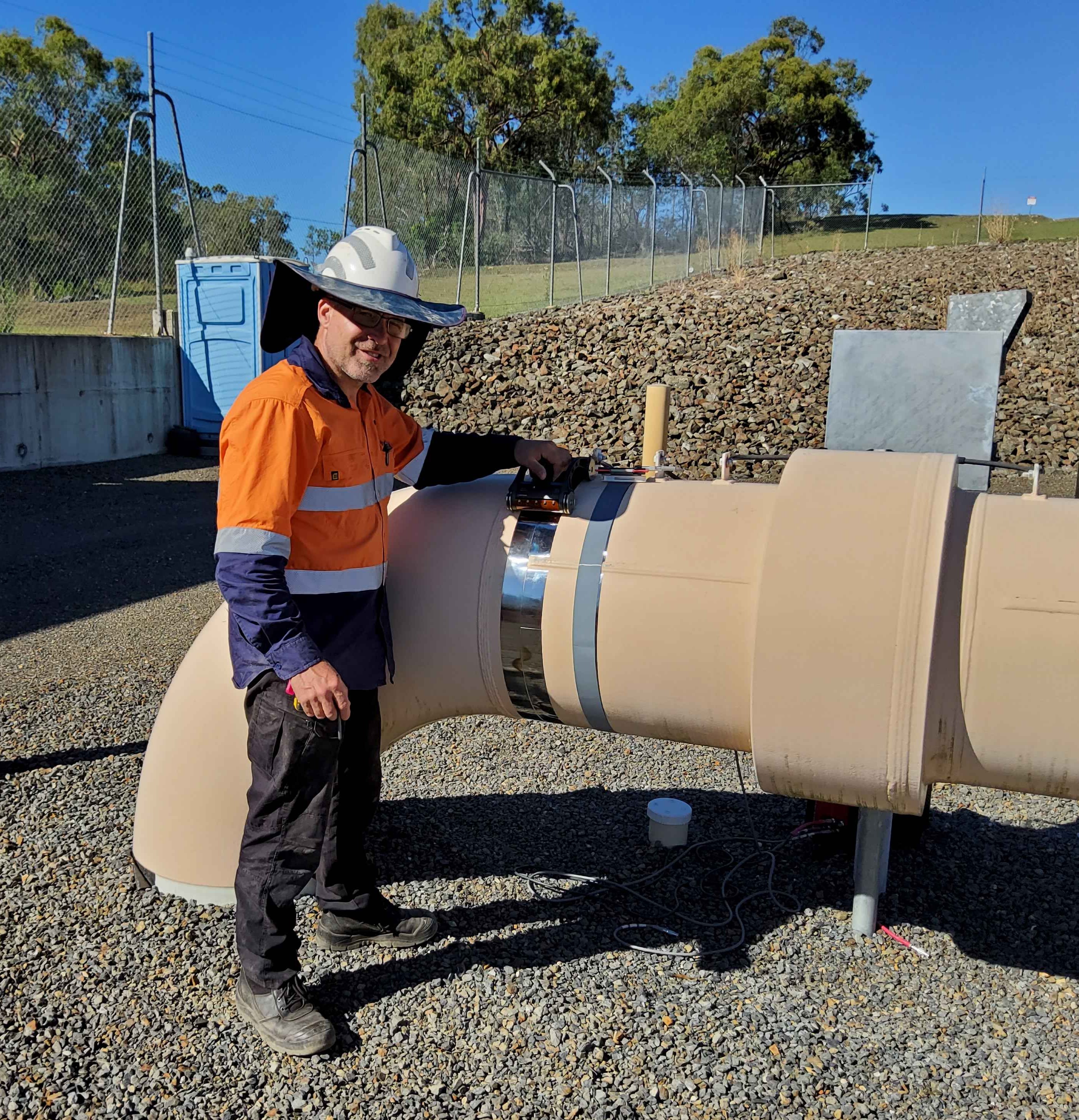
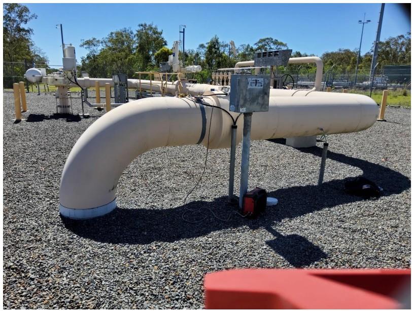
La prueba se llevó a cabo en risers de gas de acero al carbono de 10" y 24" NPS (Schedule 60), ubicados en una zona remota del centro de Queensland. Estas tuberías de penetración terrestre alcanzan típicamente una profundidad de 3 m, donde se conectan a una junta en T en un colector (manifold) o a una línea de gas principal de 40 pulgadas. Aunque estos risers suelen experimentar corrosión externa entre la línea de superficie y el colector subterráneo, no están sujetos a corrosión interna.
Se probaron risers envueltos en STOPAQ (un tipo de recubrimiento verde de consistencia similar a la goma de mascar) hace algún tiempo, y se descubrió que el STOPAQ era demasiado atenuante para obtener datos útiles, comportándose de manera muy similar al concreto y limitando el rango de escaneo efectivo a casi cero.
Muchos otros risers están envueltos en un recubrimiento bituminoso o de cinta Denso, con una cinta blanca de protección UV en la parte superior. Estas tuberías serán el objetivo de este estudio, ya que presentan una menor atenuación de la energía acústica ultrasónica que las tuberías envueltas en STOPAQ.
Los risers planteaban desafíos distintivos para los métodos estándar de END:
La solución recomendada para áreas inaccesibles y secciones de tubería enterradas son las técnicas de Ondas Guiadas EMAT (LRUT y MRUT) de Innerspec. Mientras que el LRUT permite un cribado rápido de tuberías de hasta 100 m, el MRUT proporciona una mayor sensibilidad para la calificación y cuantificación de defectos hasta a 3 m del sensor.
Todas las técnicas de Ondas Guiadas EMAT, LRUT y MRUT están disponibles con la plataforma de inspección VOLTA 2 de Innerspec.
El Ensayo Ultrasónico de Largo Alcance (LRUT) es un conjunto de técnicas avanzadas de ensayos no destructivos (END) que utilizan ondas guiadas para el cribado rápido de secciones largas de tuberías de hasta 100 m a cada lado desde el punto de inspección (+/-100 m). El LRUT es la técnica recomendada para secciones enterradas cuando el rango de inspección requerido excede los límites del MRUT.
La banda magnetostrictiva (MS) patentada incrementa la relación señal-ruido (SNR) en más de 20 dB en comparación con los collares piezoeléctricos, ofreciendo al mismo tiempo una zona muerta más pequeña y una selectividad de modo superior. No se ve afectada por las vibraciones y puede utilizarse durante la producción. La cinta axisimétrica utilizada por la técnica de Innerspec puede adaptarse a varios diámetros de tubería, eliminando la necesidad de un collar piezoeléctrico independiente para cada tamaño, lo que normalmente aumenta el coste, el peso y el volumen del sistema.
La técnica patentada LRUT FOCUS permite obtener la máxima resolución circunferencial posible para cada diámetro de tubería, basándose en los modos flexurales disponibles en el tubo. Esto se logra emitiendo pulsos con la cinta axisimétrica y recibiendo la señal con el escáner patentado en incrementos o pasos pequeños.
El Ensayo Ultrasónico de Medio Alcance (MRUT) es un conjunto de técnicas avanzadas de ensayos no destructivos (END) que utilizan ondas guiadas para inspeccionar áreas inaccesibles hasta a 3 metros (10 pies) de la ubicación del sensor con alta resolución y precisión. El MRUT complementa al LRUT ofreciendo una mayor sensibilidad, así como la calificación y cuantificación de defectos en las proximidades del sensor.
Los escáneres y sensores MRUT están diseñados para generar ondas guiadas de alta frecuencia con diferentes configuraciones de modo (Shear Horizontal, Lamb) según el tipo de aplicación y los requisitos técnicos. Para secciones enterradas e inaccesibles, la técnica recomendada es el MRUT-SH (Ondas de Corte Horizontales).
Las ondas de corte horizontales (Shear Horizontal - SH) presentan un movimiento lateral de partículas paralelo al plano de entrada (dentro del plano), con un movimiento de partículas y una fuga (leakage) mínimos hacia los materiales situados en el interior o el exterior de la estructura. La banda magnetostrictiva (MS) patentada, adherida al componente, mejora la relación señal-ruido (SNR) en >60 dB respecto a otras técnicas, convirtiéndola en la técnica de reflexión más eficiente cuando solo se dispone de acceso por un lado al área de interés.
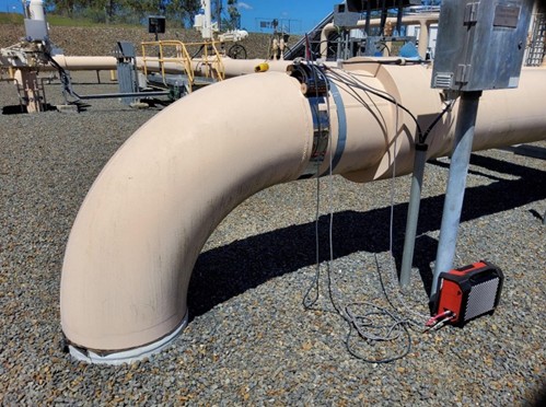
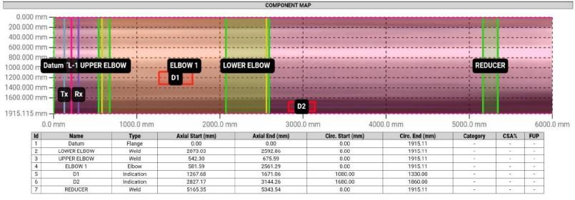
Se realizó un escaneo LRUT FOCUS en el riser de gas de 24 pulgadas NB a una frecuencia de 64 kHz. El punto de referencia (datum) se estableció en el borde de la junta aislante más cercana al codo, situándose la ubicación de la prueba a 525 mm de dicho punto de referencia.
La posición de las 12 en punto se orientó hacia arriba, con la dirección de las agujas del reloj definida mirando hacia abajo por la tubería. Se incrementó la ganancia hasta que el reductor (colector principal), ubicado aproximadamente a 3000 mm bajo tierra, fue claramente visible en el escaneo. Aunque el rango se extendió inicialmente a 10 metros, no se observaron reflexiones distintas más allá del reductor.
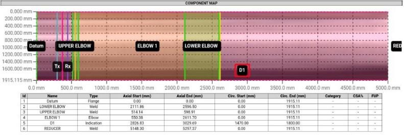
Se identificó un área de corrosión moderada bajo el nivel del suelo, la cual generó un retorno de amplitud del 61%. Las indicaciones inmediatamente posteriores a la soldadura del codo superior probablemente no sean defectos significativos; más bien, se atribuyen a la alta ganancia requerida para superar la atenuación provocada por el espesor de pared de 25.8 mm y el recubrimiento bituminoso (bituminous wrap). La indicación real del defecto se localizó por debajo de la línea de tierra, a una distancia de 2800–3000 mm desde el punto de referencia (datum) y entre los 1400–1800 mm en sentido circunferencial.
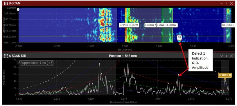
Tenga en cuenta que la energía acústica se atenúa rápidamente a medida que se propaga a lo largo de la tubería, especialmente al entrar en la sección con recubrimiento. La amplitud de cualquier reflexión debe compensarse en función de la distancia. Normalmente, se utilizan reflectores conocidos para generar una curva de Corrección de Amplitud por Distancia (DAC) para ilustrar la tasa de atenuación. Esta curva DAC está representada por la línea azul en los A-scans.
La posición vertical de esta curva a lo largo del eje X se calibra en función de la amplitud de las reflexiones de soldadura. La línea blanca representa el 100% de la altura de pantalla (Full Screen Height - FSH), mientras que las líneas roja y verde denotan intervalos de 6 decibelios (dB) utilizados para clasificar las indicaciones como menores, moderadas o severas en relación con los retornos de la soldadura.
Normalmente, se utilizan dos o más soldaduras de carrete (spool welds) como reflectores de referencia para calcular la curva DAC. En este caso, la primera soldadura se localiza en proximidad cercana al pulso inicial. La segunda soldadura es claramente visible, aunque aparece como una señal ensanchada (que abarca desde los 2.2 m hasta los 2.5 m) debido a las diferentes longitudes de trayectoria (path lengths) alrededor del codo de 90 grados.
La tercera reflexión de soldadura visible a los 5.2 m no pudo utilizarse para el cálculo de la DAC; su intensidad de señal fue significativamente superior a la de la soldadura del codo inferior, lo que sugiere que la intersección en T en el reductor actúa como un reflector mayor, superando con creces el perfil de una soldadura de carrete estándar. Por consiguiente, no se pudo calcular una DAC precisa y, en su lugar, se empleó una DAC estimada.
Basándose en esta estimación, el "Defecto 1" situado debajo del codo se clasifica como un daño de nivel moderado, lo que representa al menos una pérdida del 10% del área de la sección transversal (CSA), y justifica una investigación adicional. El reductor en el colector principal fue claramente visible a los 5.2 m, lo que confirma una inspección exitosa de todo el segmento de tubería desde el punto de referencia (datum) hasta el reductor.
Se realizó un escaneo LRUT Focus en el Riser de Gas No. 2 de 24 pulgadas NB a una frecuencia de 64 kHz. El punto de referencia (datum) se estableció en el borde de la junta aislante más cercana al codo, situándose la ubicación de la prueba a 215 mm de dicho punto de referencia.
La posición de las 12 en punto se orientó hacia arriba, con la dirección de las agujas del reloj definida mirando hacia abajo por la tubería. Se incrementó la ganancia hasta que el reductor (colector principal), ubicado aproximadamente a 3000 mm bajo tierra, fue claramente visible en el escaneo.

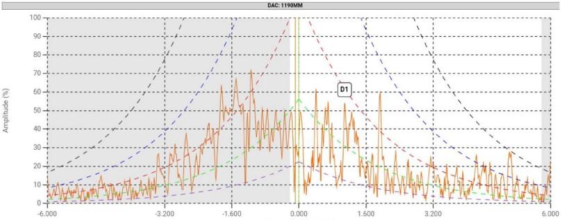

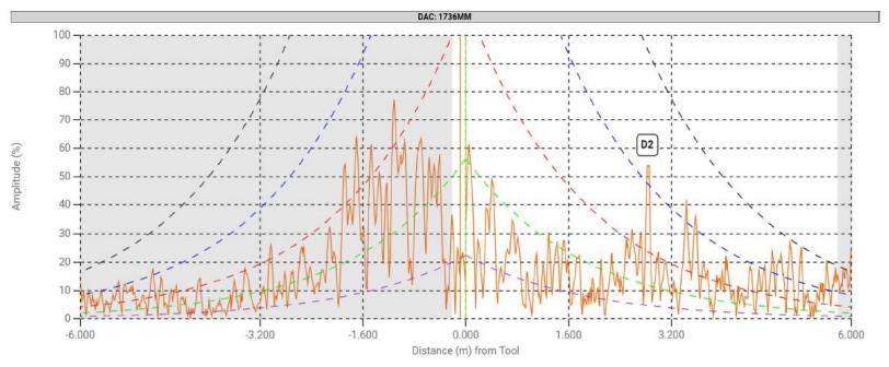
Se detectaron dos defectos de magnitud leve a moderada mediante el uso de LRUT FOCUS. El Defecto 1, localizado dentro del codo, produjo una amplitud de reflexión en el A-scan del 55% de la altura de pantalla. Por su parte, el Defecto 2, situado bajo el nivel de suelo (ground line), generó una amplitud del 53%. Cabe señalar que la energía acústica sufre una atenuación rápida a medida que se propaga a lo largo de la tubería, especialmente al ingresar en la sección revestida (wrapped section).
Basado en la DAC (Curva de Amplitud de Distancia) estimada, el Defecto 1 (localizado dentro del codo) se considera leve. Sin embargo, el Defecto 2 —situado justo bajo el nivel de suelo a 3,000 mm del punto de referencia (datum) y aproximadamente en la posición horaria de las 10— presenta un nivel de daño moderado y requiere una inspección más detallada. La reducción de la tubería principal fue claramente visible a 5,200 mm del punto de referencia, lo que confirma una inspección exitosa de todo el segmento comprendido entre el punto de referencia y la reducción.
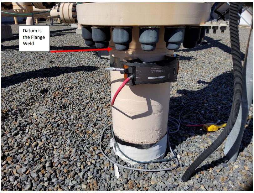
El riser de gas vertical de 10 pulgadas NB consistía en una tubería de acero al carbono Schedule 60 con un espesor de pared de 12.7 mm. Este riser fue inspeccionado inicialmente mediante LRUT LITE, lo cual reveló que el carrete vertical de 10 pulgadas estaba soldado a un codo de 90 grados aproximadamente a 1,400 mm bajo el punto de referencia (datum). Dada la longitud relativamente corta del área de interés, se realizó un escaneo de rango medio a una frecuencia de 64 kHz.
El punto de referencia se estableció en la soldadura inferior de la brida (flange) mostrada en la Figura 11. La posición de las 12 en punto se definió como el punto circunferencial orientado hacia la valla de la puerta de entrada (la ubicación de la cámara en la Figura 11), con la dirección de las agujas del reloj orientada mirando hacia arriba. La ubicación de la prueba se situó a 50 mm del datum.
El método EMAT MRUT demostró un alcance suficiente para detectar la primera y segunda soldadura de los codos de 90 grados, localizadas aproximadamente a 1,400 mm y 2,000 mm bajo el punto de referencia respectivamente. Debido a su resolución y sensibilidad superiores, se seleccionó MRUT para los escaneos de la tubería de 10 pulgadas NB. Aunque se probó un escaneo de 128 kHz para obtener la máxima sensibilidad, la profundidad de penetración fue insuficiente y las soldaduras de los codos dejaron de ser detectables.
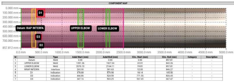
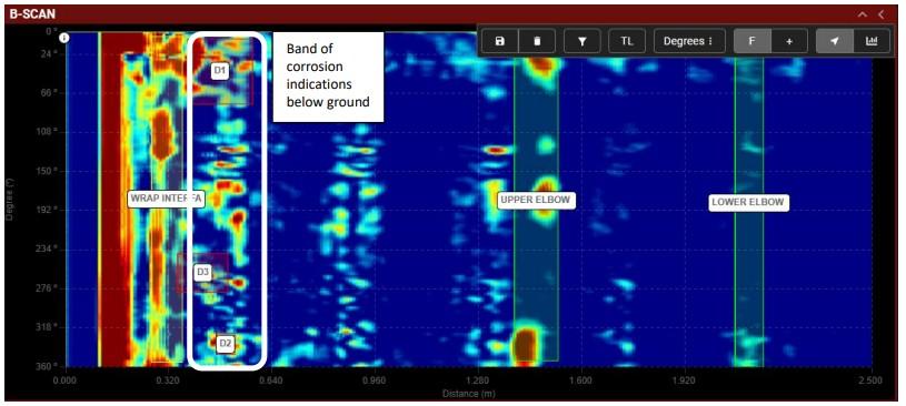
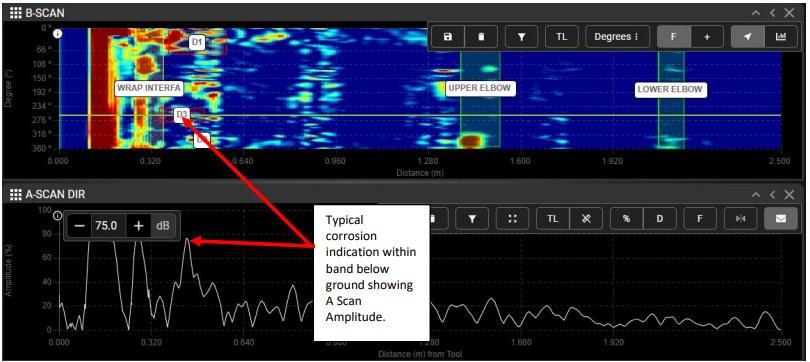
La interfaz entre la tubería desnuda pintada y la sección revestida es visible en el escaneo; sin embargo, resulta difícil distinguir entre posibles defectos y las señales de dicha interfaz. Una banda clara de corrosión moderada es evidente bajo el nivel de suelo, aproximadamente entre los 375 y 580 mm desde el punto de referencia. Las indicaciones más intensas en esta región produjeron una amplitud del A-scan del 85%, lo que sugiere que la corrosión es de moderada a severa. Adicionalmente, se observaron diversas áreas con indicaciones de corrosión menor a lo largo de toda la porción enterrada de la tubería.
El método de Ensayos No Destructivos mediante Ondas Guiadas EMAT (Ultrasonido de Largo y Medio Alcance) fue validado con éxito para la inspección de Risers de gas enterrados. Tanto los métodos de medio como de largo alcance proporcionan la confiabilidad y precisión suficientes en la detección de corrosión subsuperficial para servir como una alternativa viable a la excavación e inspección visual en la mayoría de los casos. La implementación de esta tecnología reduce significativamente el tiempo de inspección y los costes operativos, minimiza el riesgo de daños mecánicos durante la excavación y mejora la seguridad general en el sitio.
Si bien la sensibilidad de estos escaneos solo puede verificarse mediante excavación e inspección física, la capacidad de las Ondas Guiadas de Cizalladura Horizontal (Shear Horizontal Guided Waves) para detectar reflectores conocidos —tales como soldaduras de codos y reducciones hasta a 3 metros bajo tierra— es muy prometedora. Esto demuestra que las ondas superaron con éxito la alta atenuación causada por el revestimiento de la tubería y el suelo. Además, penetraron hasta una profundidad suficiente para detectar la corrosión típica, que generalmente ocurre cerca de la superficie, donde el oxígeno y la humedad son más prevalentes.
También cabe destacar que el método EMAT para la generación y recepción de ondas sonoras ultrasónicas —específicamente mediante el uso de la banda magnetostrictiva (Magnetostrictive Strip) y la plataforma VOLTA 2— supera diversas limitaciones comunes encontradas en los ensayos ultrasónicos de medio y largo alcance, tales como: